#Assembling arduino robotic arm how to
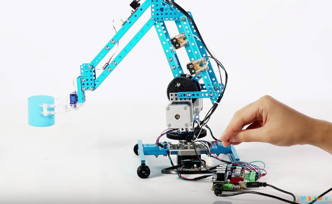
If you don't have a robotic arm kit (and doesn't want to buy or build one) you can still use it to learn something about Arduino programming, and how to interface an Wii Nunchuk to your own projects. There are several ways you can use this tutorial. For this project I also wanted to experience a different method for controlling a robotic arm: using a Nintendo Nunchuk! They are cheap, easy to find, and have a bunch of sensors. In this tutorial I show you how to mount a robotic arm, and how to program it using an Arduino Mega. They can also be found in space exploration, subsea remote operated vehicles, and even in medical applications!Īnd now you can have a cheaper version of them at your own home, office or lab! Tired of doing a repetitive job? Program your own robot to help you. The flex sensors on the glove send signals based off the position change, when the fingers on the gloves move the change in position sends a signal to the arduino which then calls for the 3-D printed “hand” to change in the same proportion.Robotic arms are awesome! Factories all over the world have them, where they paint, solder and carry stuff with precision. The basis of the program is similar to the knob turning program in arduino, and works overall as potentiometer. There is also bars running across the breadboard which connects the negative columns together on either end of the board and the positive columns together on either end of the board.Īdditional note- longer wires can be used to extend the amount of slack available between the breadboard and the glove or the breadboard and the 3-D printed arm if needed The final components to the wiring are the connections from the 5V power on the arduino to the positive column and the ground (GND) connects to the negative column. (Note- Most of the physical connections of the wires not in the breadboard were soldered, and shrink wrap was used to protect the connections) On the fritzing file there is a secondary more clear sketch which shows the positive, negative and signal connections. Then the other flex sensor connection runs to the breadboard and connects to the positive column on the breadboard. The three analog pins I used were A0, A1, A2. The resistor connects with one end to the flex sensor and the other connects to a wire which runs to the breadboard before hooking up to the arduino analog in pins. The wire runs straight to the negative terminal through the breadboard. On the side where you connect the signal and negative wire attach both a 22k resistor and a secondary wire.

The side with a thicker patterned side is a connection to the positive terminal. In my set up pin 9 connects to the base servo and is controlled by the thumb In my set up pin 10 connects to the top servo and is controlled by the middle finger In my set up pin 11 connects to the middle servo and is controlled by the pointer fingerĢ) Glove Connections There are two connections available on the flex sensors, on the side with the thin line runs the connection to both the signal and the negative terminal. Finally the yellow signal wires connect to the arduino. The red wires on the servo connect to the positive regions, namely the positive column on the breadboard. The black wires on the servo connect to the negative regions, namely the negative column on the breadboard. 1) Connections from the breadboard and arduino to the 3-D printed “arm” 2) Connections from the breadboard and arduino to the glove.ģ-D Printed Arm connections The wires hooked up to the pins 11, 10, 9 as well as the positive and negative regions are connected to the 3 different servos. The wiring can be best looked at in two different parts.

The image of the wiring exactly as I have it set up is in the fritzing file.


 0 kommentar(er)
